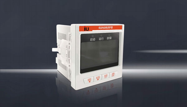
Intelligent low-voltage motor protector YY20KS
The YY20KS series intelligent low-voltage motor protector is a variety of products designed by our company for low-voltage motors
Developed based on fault characteristics, it is a highly cost-effective, stable and reliable product that integrates relay protection, measurement
A low-voltage motor protector that integrates control and communication. The protector collects the protected motor circuit
Calculate the data of three-phase current, three-phase line voltage, grounding current, etc., and record them with the protector
Compare the setting information of various protection functions, and when the protection action conditions are met, drive the relay output,
So as to achieve the goal of reliable protection of the motor. The YY20KS low-voltage motor protector is composed of the protector host
MCT current transformer consists of two parts. Protectors can achieve measurement functions, protection functions, and electric motors
Start/stop control function and remote communication function YY20KS use communication function as an important tool for remote management
Section, supports MODBUS-RTU communication bus protocol.
The YY20KS intelligent low-quality motor protector meets the following safety standards:
GB/T4048.1-2012 General Principles for Low Voltage Switchgear and Control Equipment,
GB/T4048.4-2010 Low voltage switch settings and control settings Electromechanical contactors and motor starters,
GBfF14O48.5-2008 Low voltage switchgear and control settings, control circuits, electrical appliances and switch components
Part 1: Electromechanical Control Circuit Electrical Appliances
GBTTI4048.6-2008 Low voltage switchgear and control equipment
Part 2: AC Semiconductor Motor Controllers and Starters
Product features
1. Can be used for comprehensive protection of various current specifications of motors with voltage levels of 0.66KV and below.
2. YY20KS is equipped with MCT (three-phase integrated current transformer), with a maximum current specification of 400A.
3. The intelligent low-voltage motor protector monitors the current and voltage of the low-voltage MCC (Motor Control Center) circuit The electric motor is fully protected by parameters such as leakage current (with multiple protection functions such as startup timeout, overload, locked rotor, phase failure, imbalance, ground fault, short circuit, under load overvoltage, under voltage, overflow fault tripping circuit breaker, etc.), and can also be equipped with leakage protection tE time protection "anti shake" function and under voltage restart function
4. Using a wide temperature Chinese LCD and a combination of high brightness indicator lights to display operating status and data.
5. Programmable settings allow for easy on-site modification of setting current, protection settings, and other parameters.
6. Optional 1 RS485 communication interface, using MODBUS-RTU protocol to communicate with the backend network.
7. Optional configuration includes 1 channel of DC4-20mA analog variable transmission output to the backend industrial computer.
8. Provide 6-way switch input acquisition and 3-way relay output, suitable for various starting control methods
9. The working power supply adopts AC/DC universal, wide range input design, and the power supply voltage range is AC/DC85V-265V
10. The protector adopts a panel opening screen installation method (with an opening size of 76mmx76mm).
11. It has the function of recording 32 fault events and measuring active/reactive energy.
Product selection instructions
Note 1: Select the appropriate current specification based on the motor nameplate current or rated power (the "current specification" of the protector should be slightly greater than the motor nameplate current), when the motor nameplate current is> At 400A, a protective current transformer with an external secondary current of 5A is required (one for three-phase A, B, and C, and the selection information can be found on page 58)
Note 2: Multiple optional functions can be selected at the same time (among which, choose one from three options: electric actual sampling protector, "ground actual sampling protector," and ground fault synthesis calculation protection. The default configuration is "ground fault synthesis calculation protection")
Note 3: The length of the three-phase current transformer (MCT) connection line for the protective device is 1 meter as standard, and three sizes of 1 meter, 3 meters, and 5 meters are available
TECHNICAL INDEX
functional configuration
External dimensions and installation method
Installation method of the protector host: YY20KS motor protector, adopts panel embedded installation method, and pre opens a 76x76mm square hole on the door panel of the distribution cabinet,
Remove the fixing cards on both sides of the protector, insert the protector into the installation hole from the front of the door panel, then insert the matching fixing cards into the card slots on both sides of the protector, and then push forward to secure the protector
The protector can be securely fixed to the door panel.
External dimensions and installation method
External dimensions and installation method

1. MCT6.3 (D=9.5mm), suitable for dry 2A and 6.3A (three-phase main circuit cables passing through three at once in the local direction) Φ 9.5mm threading hole), with
External CT input signals 1A and 5A for circuits greater than 400A (secondary lines of three-phase external CT, passing through three turns in the same direction) Φ 9.5mm abandoned line
Hole)
2. MCT30 (D=15mm), suitable for 30A (three-phase main circuit cables passing through 3 in the same direction at once) Φ 15mm shoreline
Hole)
3. MCT100 (D=20mm), suitable for 100A (three-phase main circuit cables passing through 3 in the same direction at once) Φ 20mm threading hole),
4. MCT200 (D=25mm), suitable for 200A (three-phase main circuit cables passing through 3 in the same direction at once) Φ 25mm abandoned wire hole
5. MCT400 (D=40mm), suitable for 400A (three-phase main circuit cables passing through three banks in the same direction) Φ 40mm threading hole)
Note 1: When the current is> When 400A or using a frame circuit breaker, an external protective current transformer with a secondary current of 5A is required (one for three-phase A, B, and C). The secondary 5A current signal is defined as MCT perforation, and one turn in the same direction passes through the three-phase current transformer MCT6.3 of the protective device. The CT ratio can be set inside the protective device.
Terminal definition and wiring
YY20KS Protection mode wiring diagram

In protection mode, the normally closed contact (21 # 22 #) of the internal relay D01 of the protector is connected in series in the coil circuit of the control motor contactor KM. When the protector is powered on, it can be pressed on
The "Start" button in the picture connects the KM coil circuit to allow the KM auxiliary contact to engage and self navigate In the QF closed state of the main circuit, the main contact of the contactor is engaged, causing the motor to three-phase
Power on start. When the protector detects a fault set as a trip output and the delay time is up, the protector performs a gap trip action, causing the normally closed point of relay D01 to disconnect and make contact
Release KM and stop the motor. After the fault trips, it is necessary to press and hold the reset button for more than 3 seconds to clear the fault indication. Relay DO1 will return to its original state and enter the start ready state,
Allow the motor to start again
Note 1: In protection mode, the start/stop operation must be completed using an external button, and the start/stop button operation on the protector panel is invalid. The remote start in the figure above
The parking and reset buttons are all of the jog type
Note 2: The MCT in the diagram is a protective device with a built-in current transformer, with a current specification of ≤ 4400A. The cables of the three-phase main line are threaded in the same direction once MCT outgoing line from
The 4-core terminals are directly plugged into the three-phase current input port (41 # 46 #) of the protector, when the rated current of the motor is> At 400A, the electricity of the three-phase main line
The cable passes through three external protection CTs (P1 in, P2 out) in advance, and the 5A current lines on the secondary side of the three external CTs are threaded in the same direction as defined by the MCT wellbore, with one turn
Overprotector MCT6.3 three-phase hole
Note 3: When the fault current detected by the protector is greater than the maximum breaking capacity current of the contactor (the maximum breaking current of the contactor must be set in advance in the protector system parameters):
If it is 9 times IE, first keep DO1 in the original closed state (do not trip the contactor at this time, otherwise the main contact of the contactor is easily damaged), and wait for "overflow fault relay life"
Pull action (pulse), control the circuit breaker to open to protect the motor and circuit, delay for I seconds before tripping off the DOI and disconnecting the contact! Device, reporting overflow fault two
Note 4: When selecting the leakage protection function, a suitable residual current transformer with a suitable threading aperture should be selected (the motor circuit A, B, and C three-phase lines should pass through the matching residual current mutual protection at the same time)
Sensor selection information can be found on page 56. When selecting the grounding protection function, a suitable grounding current transformer with a secondary current of 5A and a suitable threading aperture should be selected (customer)
Household self configuration
Note 5: The internal relay DO3 of the protector is a programmable relay. When the protector does not open the undervoltage restart function, the function is defined as the fault alarm output relay I when it is protected
When the protector opens the undervoltage restart function, it starts the output relay and is connected to both ends of the start button, which can be used for starting the shaking power page and starting the undervoltage page.
YY20KS Direct start control contactor mode wiring diagram

In direct start mode, when the protector is powered on and enters the ready to start state, the protector displays "Direct Start". When the protector receives the start command, the internal relay 3DOI
If (22 # -23 #) is engaged, the contactor KM will be energized and engaged. During the startup process, the "Start" light will be on, indicating "Starting". The startup is completed, the "Start" light will be off, and "Run" will be displayed
The light is on, and the protector displays "Running". When the protector receives a stop command or a protection trip occurs, relay DO1 opens and contactor KM is released,
Electric motor shutdown | After the shutdown process is completed and enters the ready to start state, the protector displays "Directly start two faults. After tripping, press the reset button for more than 3 seconds to cure the fault."
Instructions
Note 1: In the direct start mode, the start, stop/reset operations can be controlled by the protector operation button, remote button/DCS switch, and background communication control
One of the methods is used to complete (the operation permissions need to be selected in the system settings of the protector: press key, remote, and program control. After selecting the operation permissions, the three control methods are:
Only one selected control method in the formula is effective for control. The external joint flight protection function can be selected to be turned off or on, and the input type can be selected as normally closed or normally open,
It can be used for emergency parking by setting a delay time. The remote start button and stop/reset button in the above figure are all of the jog type, and the short press of the stop reset button is
Park, long press> Stop and reset in 3 seconds
Note 2: The MCT in the figure is a protective device with a built-in current transformer, with a current specification of ≤ 4400A. The cables of the three-phase main line are threaded in the same direction at once, and the MCT outgoing line is from
The 4-core terminals are directly plugged into the three-phase current input port (41 # 16 #) of the protector, when the rated current of the motor is> At 400A, the electricity of the three-phase main line
The cable passes through three external protection CTs (P1 in, P2 out) in advance, and the 5A current lines on the secondary side of the three external CTs are defined as MCT perforations, with one turn in the same direction
Pass through the three-phase hole of protector MCT6.3
Note 3: When the fault current detected by the protector is greater than the maximum breaking capacity current of the contactor (the maximum breaking current of the contactor must be set in advance in the protector system parameters),
If it is 9 times IE, first keep the relay DCH in the original closed state (do not trip the contactor at this time, otherwise the main contact of the contactor is easily damaged), and wait for the overflow fault to continue
The electrical "suction action (pulse) controls the circuit breaker to open to protect the motor and circuit. After a delay of I seconds, release the electrical DOI, disconnect the contactor, and report an overflow fault.
Note 4: When selecting the leakage protection function, a suitable residual current transformer with a suitable threading aperture should be selected (the motor circuit A, B, and C three-phase lines should pass through the matching residual current transformer at the same time),
Please refer to page 56 for selection information. When selecting the grounding protection function, an appropriate abandonment aperture should be selected
YY20KS Direct Start Control Circuit Breaker Mode Wiring Diagram (Frame Circuit Breaker Circuit)

In YY20KS direct start control circuit breaker mode, when the protector is powered on and enters the start ready state, the protector displays "circuit breaker start". When the protector receives the closing (start)
When the command is given, the internal relay A (copper closing relay) is engaged, and the circuit breaker closing coil is energized. The circuit breaker is closed, and the motor starts running. During the starting process, the "start" light is on,
Kun indicates "starting". The "start" light is off, the "run" light is on, and the protector displays "running" when the protector receives a stop command or a protection trip occurs
When the action occurs, relay B (tripping relay) is energized, the circuit breaker excitation coil is energized, the circuit breaker opens, the motor cools and stops, and after the stopping process is completed, it enters the
When in the ready state, the protector displays "circuit breaker start" fault. After tripping, the "reset button" must be pressed to clear the fault indication
Note 1: The closing (start) and parking/resetting operations can be controlled by three methods: the protector operation button, remote button/DCS switch signal command, and background communication control
One of the three control methods is required to complete (by selecting the operation permissions in the system settings of the protector: button, remote, and program control). After selecting the operation permissions, only
A selected control method is only effective for control. The external interlocking protection function can be selected to be turned off or on, and the input type can be selected as normally closed or normally open, which can be achieved through
Set the delay time for emergency stop. The remote close (start) button and stop/reset button in the above figure are all in a jog mode, and the stop/reset button is short
Press to stop, long press> Stop and reset in 3 seconds
Note 2: When a high-power motor is directly controlled by a frame circuit breaker, the copper bars of the three-phase main circuit are pre threaded through three external protection CTs (PI in, P2 out), and the external
The 5A current line on the secondary side of the partial CT is connected to the protector by inserting the 4-core terminal of the MCT6.3MCT outgoing line directly into the protector, with one turn in the same direction passing through the protector MCT6.3MCT
Input ports for three-phase current (41 #~46 #)
Note 3: When selecting the leakage protection function, a suitable residual current transformer with a suitable threading aperture should be selected (the motor circuit A, B, and C three-phase lines should pass through the matching residual current mutual protection at the same time)
Sensor, selection information can be found on page 56 When selecting the grounding protection function, a suitable grounding current transformer with a secondary current of 5A and a suitable threading aperture should be selected (customer)
Household self configuration
Note 4: In the circuit breaker closing coil and tripping coil circuits of the secondary control circuit shown in the figure, the instrument is built as shown in the figure, and the normally closed and normally open auxiliary contacts of the circuit breaker are respectively connected (if
If the output mode of internal relays A and B in the protector is set to level mode, the auxiliary contact must be connected. If the output mode of internal relays A and B in the protector is set to short
Time pulse mode Depending on the situation, it may not be accepted.