Comprehensive low-voltage motor protector YY20MS
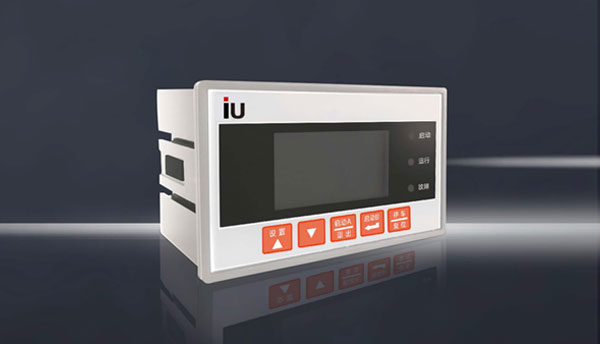
The YY20MS series comprehensive low-voltage motor protector is developed by our company in response to various fault characteristics of low-voltage motors. It is a low-voltage motor protector with extremely high cost performance, stability and reliability, and integrates relay protection, measurement, control and communication. The protector collects data such as three-phase current, three-phase line voltage, and ground current in the protected motor circuit. These data are calculated and compared with the various protection function setting information recorded by the protector. When the protection action conditions are met, the driver Relay output to achieve the purpose of reliably protecting the motor. YY20MS low-voltage motor protector consists of three parts: the protector host, the display module, and the three-phase current transformer MCT. The protector host can operate without the display module to realize measurement functions, protection functions, motor start/stop control functions and remote communication functions. The display module serves as an auxiliary device and can be configured as needed. YY20MS uses communication functions as an important means of remote management: Means, support MODBUS-RTU, PR0F1BUS-DP multiple bus protocols. YY20M comprehensive low-voltage motor protection meets the following safety requirements
YY20KS intelligent low-quality motor protector complies with the following safety standards:
GB/TI4048.1-2012 General principles for low-voltage switchgear and control equipment,
GB/TI4048.4-2010 Low-voltage switch settings and control settings for electromechanical contactors and motor starters ,
GBfF14O48.5-2008 Low-voltage switchgear and control settings Control circuit appliances and switching elements
Part 1: Electromechanical control circuit appliances
GBTTI4048.6-2008 Low-voltage switchgear and control equipment
Part 2: AC semiconductor motor controllers and starters
Features
1. It can be used for comprehensive protection of motors with voltage levels of 0.66KV and below and various current specifications.
2. YY20MS is equipped with MCT (three-phase integrated current transformer), and the maximum current specification reaches 400A.
3. The comprehensive low-voltage motor protector comprehensively protects the motor by monitoring the current, voltage, leakage current and other parameters of the low-voltage MCC (Motor Control Center) circuit (including start-up timeout, over-cutting, blocked rotor, phase failure, unbalance, ground fault, short circuit , underload, overvoltage, undervoltage, phase sequence disorder, overflow fault ground circuit breaker and other protection functions, and optional leakage protection, overtemperature protection, tE time protection "anti-shock" function, and under voltage loss restart function).
4. Use wide-temperature Chinese LCD and bright indicator lights to display operating status and data.
5. Programmable settings, parameters such as setting current and protection setting can be easily changed on site.
6. Optional 1-way or 2-way RS485 communication interface, using MODBUS-RTU protocol to communicate with the backend network, or PROFIBU&DP communication interface, PROFIBUSV1.0 version can communicate with IR protocol.
7. Optional 1-channel DC4~20mA analog St transmission output to the background industrial computer.
8. Provides 8 channels of switching input acquisition (can be expanded to 10DI) and 4 channels of electrical output, which can be applied to a variety of starting control methods.
9. Power supply voltage: AC/DC85V-265V (universal wide range of AC and DC), convenient for design and application, and the protector can be expanded to dual power input. 10. The main body of the protector adopts 35mm standard guide rail installation method, which is convenient for installation and disassembly. The display module is screen-mounted (the opening size is 965mx55mm). 11. It has the function of recording 8 fault events, the operation information statistics function, and the active/reactive power meter. Function.
Product selection instructions

Note 1: Select the appropriate current specification based on the motor nameplate current or rated power (the "current specification" of the protector should be slightly larger than the motor nameplate current). When the motor nameplate current is >400A, an external secondary current of 5A is required. Transformer (one for each of A, B, and C phases, see page P58 for selection information).
Note 2: Multiple optional functions can be selected at the same time (including "leakage actual mining protector, grounding actual mining protection and "ground fault synthetic calculation protection"). The default configuration is "ground fault synthetic calculation protection, dual communication mode" You can choose M2 (2 RS485 interfaces, MODBUS-RTU protocol) or MP (1 RS485 interface/MODBU9RTU protocol, plus 1 PROFIBUS-DP I interface)
Note 3: The protector body and display module use standard DB9 serial ports When ordering, the standard length of the DB9 serial port cable must be specified. The DB9 serial port cable comes standard with 1 meter and can be selected in three lengths: 1 meter, 3 meters, and 5 meters.
Technical indicators
Function configuration
Protector body dimensions (unit: mm)
Note: The protector body adopts the standard 35mm rail installation method, and the body and the display module are connected using the standard DB9 serial port cable. The DB9 serial port cable comes standard with 1 meter, and is available in three lengths: 1 meter, 3 meters, and 5 meters.
Display module overall dimensions (unit: mm)
Schematic diagram of display module installation (recommended opening size is 96.5mmx55mm)
Supporting three-phase integrated current transformer overall dimensions and installation method:
The supporting three-phase integrated mutual condensation device (MCT) is divided into 5 specifications and models:
1. MCT6.3 (D=9.5mm), suitable for 2A and 6.3A (the three-phase main circuit cable passes through 3 Φ9.5mm threading holes at one time).
2. MCT30 (D=15mm), suitable for 30A (the three-phase main circuit cable passes through three Φ15mm shoreline holes in the same direction at one time).
3. MCT100 (D=20mm), suitable for 100A (the three-phase main circuit cable passes through 3 Φ20mm threading holes in the same direction at one time).
4. MCT200 (D=25mm), suitable for 200A (the three-phase main circuit cable passes through 3 Φ25mm wire abandonment holes in the same direction at one time).
5. MCT400 (D=40mm), suitable for 400A (the three-phase main circuit cable passes through three Φ40mm threading holes in the same direction at one time).
Note 1: When the current is >400A or a frame circuit breaker is used, an external protective current transformer with a secondary current of 5A (one for each of the A, B and C phases) is required. The secondary 5A current signal is defined according to the MCT hole. One turn in the same direction passes through the protector's three-phase current transformer MCT6.3, and the CT transformation ratio can be set in the protector.
Three-phase current transformer installation method
Open two Φ4.5mm round holes with a spacing of LI at appropriate positions in the cabinet, and use two M4 bolts, nuts, spring washers, etc. to fix the three-phase current transformer.
Terminal definition and wiring
Typical control mode wiring diagram: The following mainly lists the three control mode wiring diagrams of typical applications of YY20MS: protection mode, direct start control contactor mode, direct start control break mode wiring diagram. The remaining control mode wiring diagrams (bidirectional reversible starting mode, star/delta starting mode, two-speed motor starting mode, etc.)
YY20MS protection mode wiring diagram
In the YY20MS protection mode, the normally closed contact of DO3 (stop/trip relay) in the protector is connected in the coil circuit that controls the motor contactor KMI. When the protector is powered on, DO3 remains closed and is waiting to start the motor. When the "start button" is pressed, the KM1 coil is energized. The KMI main contact in the motor's main circuit and the KMI auxiliary contact connected in parallel to both ends of the "start button" attract and the self-locking motor starts running normally after being energized. When the "stop" button is pressed or the protector detects a tripping fault, DO3 (stop/trip relay is disconnected and the contactor KMI is released. After the motor stops and fails to trip, the reset button needs to be pressed for more than 3 seconds to clear the fault. Instruction, D03 (stop/trip relay) resumes closing and enters the start-ready state, allowing the motor to start again.
Note 1: The MCT in the picture is a protector with built-in current transformer ≤ 400A current specification. The cables of the three-phase main line are cored once in the same direction. The 4-core terminals of the MCT lead wire are directly plugged into the three phases of the protector. Current input port (41#46#), when the rated current of the motor is >400A, the cables of the three-phase main line are passed through 3 external protection CTs (P1 in, P2 out) at one time, and the 3 external CTs are connected to the secondary side. The 5A current line is connected to the three-phase current input port (41#46#) as defined, and the S2 terminals of the three external protection CTs are connected to the ground.
Note 2: When the fault current detected by the protector is greater than the maximum breaking capacity current of the contactor (the maximum breaking current of the contactor must be set in the protector system parameters in advance, such as 9 times Ie), first keep D03 in the original state (Do not trip the contactor at this time, otherwise the main contact of the contactor will be easily damaged). After the "overflow fault relay pulls in (pulse) and controls the circuit breaker to open to protect the motor and circuit, delay 1 second before action D03 (stop/trip relay), open the contactor and report an overflow fault.
Note 3: When selecting the leakage protection function, a residual current transformer with a suitable threading hole diameter should be selected (the three-phase wires of the motor circuit A, B, and C pass through the matching residual current transformer at the same time. See page P56 for selection information). When selecting the grounding protection function, a grounding current transformer (customer-configured) with a secondary current of 5A and a suitable abandoned wire aperture should be selected.
YY20MS direct start control contactor mode wiring diagram
In the YY20MS direct start control contactor mode, the protector is powered on and enters the start-ready state, and the display module displays "Direct start." When the protector receives the start command, the internal relay A suction table contacts SKM1 and is powered on, starting the process. During the process, the 'Start' light is on and 'Starting' is displayed. After starting, the 'Start' light is off, the 'Run' light is on and the display module displays 'Running'. When the protector receives a stop command or a protection tripping action occurs, relay A is disconnected. , contactor KM1 is released, and the motor stops. After the parking process is completed, when it enters the start-ready state, the display module displays "Direct start fault. After tripping, you need to press the reset button for more than 3 seconds to clear the fault indication."
Note 1: In direct start mode, start, stop/reset operations can be completed by one of the three control authority operations: local, remote, and program control. The local/remote operation authority is selected by the ZK switch connected to DI5: when DI5 is disconnected to low level, local authority (protector press control), when DI5 is connected to high level, remote authority (remote D1, program control, The default is Dl switch cabinet button/DCS open Meixing command control. When the host computer is set to program control, the monitoring system controls the motor start/stop). If the protector button is not needed to control the motor start/stop, the ZK switch contact can be short-circuited directly. , fixed as remote operation permission. The "Emergency Stop" button is the same as the red reset button on the protector host and is not restricted by DI5 operation authority. The buttons that act on DI in the above picture are all inching type. Short press the stop/reset button to stop, and long press >3 seconds to stop and reset.
Note 2: The MCT in the picture is a protector with built-in current transformer, ≤ 400A current specification protector. The cables of the three-phase main line are cored once in the same direction. The 4-core terminal of the MCT lead wire is directly plugged into the protector. Three-phase current input port (41#46#), when the rated current of the motor is >400A, the cables of the three-phase main line are passed through 3 external protection CTs (PI in, P2 out) at one time, and the 3 external CTs are The secondary side 5A current line core is defined to be connected to the three-phase current input port (41#46#), and the S2 terminals of the three external protection CTs are connected to the ground.
Note 3: "Overflow fault grounding/leakage fault action" first trips the circuit breaker and delays for 1 second to open the contactor.
Note 4: When selecting the leakage protection function, a residual current transformer with a suitable threading aperture should be selected (the three-phase wires of the motor circuit A, B, and C pass through the matching residual current transformer at the same time.
YY20MS direct start control circuit breaker mode wiring diagram (frame circuit breaker circuit)
In YY20MS direct start control circuit breaker mode, when the protector is powered on and enters the start-ready state, the display module displays "Circuit breaker start 2". When the protector receives the closing command, the internal relay A (table gate relay) is closed, then The circuit breaker closing coil is energized, the circuit breaker is closed, and the motor is started to run. During the starting process, the "Start" light turns on and "Starting" is displayed. After the startup is completed, the "Start" light goes out, the "Run" light turns on, and the display module displays "Running". When the protector receives an opening command or a protective tripping action occurs, relay B (idle relay) is closed, then The shunt coil of the circuit breaker is energized, the circuit breaker is opened, and the motor is cooled and stopped. After the parking process is completed, when it enters the start-ready state, the display module displays that the circuit breaker starts fault and needs to press the remote "reset button" or the protector host to trip. The red reset button clears the fault indication.
Note 1: Closing and opening. Reset control can be completed by any one of the three control authority operations: local, remote, and program control. The local/remote operation authority is selected by the ZK switch connected to DI5: when D15 is disconnected to low level, local authority (protector button control), when D15 is connected to high level, remote authority (remote DI, program control, default It is controlled by DI-switch cabinet button DCS switching value command. When the host computer is set to program control, the monitoring system controls the motor start/stop.) If the protector button is not needed to control closing/opening, the ZK switch contact can be directly short-circuited and fixed. for remote operation permissions. "External fault F serves as an emergency stop signal. Like the red reset button on the protector host, it is not restricted by DI5 operation authority. The buttons acting on D1 in the above figure are all inching type. Short press the opening/reset button to open the gate. Press and hold for >3 seconds to open and reset the gate.
Note 2: When a high-power motor is directly started and controlled by a frame circuit breaker, the copper bars of the three-phase main line must pass through three external protection CTs (PI in, P2 out) in advance, and the secondary side current of the three external CTs will be 5A. The wires are connected to the three-phase current input port (41#46#) and the S2 terminals of the three external protection CTs according to the definition and are grounded.
Note 3: When selecting the leakage protection function, a residual current transformer with a suitable threading aperture should be selected (the three-phase wires of the motor circuit A, B, and C pass through the matching residual current transformer at the same time). When the grounding actual mining protection function is selected, A grounding current transformer (customer-prepared) with a secondary current of 5A and a suitable threading hole diameter should be selected.
Note 4: In the circuit breaker closing coil and trip coil circuit of the secondary control circuit in the above figure, it is recommended to connect the normally closed and normally open auxiliary contacts of the circuit breaker respectively as shown in the figure.
Low voltage motor protector function configuration comparison table
Motor protector current specification selection reference table
Note: The data in the table refer to the four-pole squirrel cage motor operating at AC380V, 50Hz, 1500 rpm/