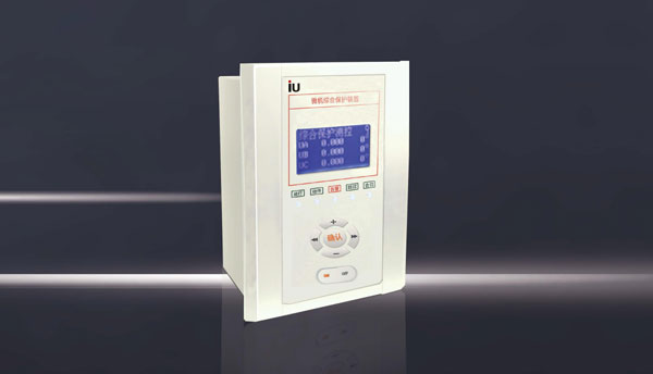
YYR8600 series ring main unit microcomputer protection device is suitable for measurement and protection of lines, busbars, capacitors, factory transformers with voltage levels of 35KV and below, as well as power supply auto-switching for incoming line equipment. Since the installation thickness is only 80mm, it is very suitable for installation in On the ring main unit. This series of microcomputer protection devices can be installed locally in switch cabinets or can be installed in a centralized panel. It provides communication interfaces and can be used together with other protection and automation equipment to form an automation system through communication interfaces.
GB6162-85 "Electrical interference test of static relays and protective devices"
GB7261-87 "Basic test methods for relays and relay protection devices"
GB2887-89 "Computer Station Site Technical Conditions"
GB 14258-93 "Technical Regulations for Relay Protection and Safety Automation Devices"
GB 50062-92 "Design Specifications for Relay Protection and Automation Devices of Electric Power Installations"
DL/T 527-2002 "Static relay protection device inverter power supply technology"
IE870-5-103 "Relay Protection Information Interface Standard" GB/T15145-
94 "General Technical Conditions for Microcomputer Line Protection Devices"
GB/T16435.1-1996 "Remote control equipment and systems and interfaces (electrical characteristics)"
GB/T17626.2 "Electrostatic discharge immunity test"
GB/T17626.3 "Radio frequency electromagnetic field radiation immunity test"
GB/T17626.4 "Electrical Fast Transient Burst Immunity Test"
GB/T17626.5 "Surge Impact Immunity Test"
GB/T17626.6 "Conducted disturbance immunity test induced by radio frequency fields"
GB/T17626.8 "Power frequency magnetic field immunity test"
GB/T17626-1998 "Electromagnetic compatibility testing and measurement technology"
GB/T14537-1993 "Impact and Crash Test of Measuring Relays and Protective Devices"
A Insulation resistance: Under normal test atmospheric conditions, use a megohmmeter with an open circuit voltage of 500V to measure the insulation resistance value between the live circuit part of the device and the non-charged metal and shell, as well as between circuits that are not electrically connected; normal test Under atmospheric conditions, the insulation resistance of each circuit is not less than 100MΩ.
B Dielectric strength: Under normal test atmospheric conditions, the device can withstand a power frequency withstand voltage test with a frequency of 50HZ and a test voltage of 2000V lasting 1 minute without breakdown, flashover and component damage.
C Impulse voltage: Under normal test atmospheric conditions, the device's DC input circuit, AC input circuit, signal output contact circuits to ground and between circuits can withstand the short-term impact of (1.2/50) μs standard lightning waves Voltage test, open circuit test voltage 5KV, no insulation damage.
D Burst interference: The device can withstand the 1MHz and 100kHz burst interference tests specified in GB/T14598.13-1998 (idt IEC60255-22-1:1988). The test severity level is Level III, the test voltage is 2.5KV in common mode and 1kV in differential mode.
E Radiated electromagnetic field interference: The device can withstand the harsh level III radiated electromagnetic field interference test specified in GB/T14598.9-1995 (idt IEC60255-22-3:1989), that is, the test field strength is 10V/m.
F Electrostatic discharge interference: The device can withstand the severity level specified in GB/T14598.14-1998 (idt IEC60255-22-2:1996) as level IV, that is, the contact discharge test voltage is 8KV, the allowable deviation is ±5%, and the air discharge The test voltage is 15KV and the allowable deviation is ±5% electrostatic discharge interference test.
G Fast transient interference: The device can be tested according to the severe level IV fast transient interference specified in GB/T14598.10-1996 (idt IEC60255-22-4:1992), that is, the test voltage is 4KV, and the allowable deviation is ±10 %.
Working temperature: -25℃ ~+70℃ Storage temperature: -40℃ ~+85℃ Humidity: 5~95%RH
A Working conditions: Able to withstand vibration response and impact response with severity level I;
B Transportation conditions: Able to withstand severe level I vibration durability, impact durability, and collision.
Product selection instructions
Dimensions
The installation method
is to install in the front. Open a hole with a distance of 144 (horizontal) , after setting it up from the front, then use the M3 screws matching the 4 devices from the first side to determine.


